Section 4 Mechanical Design
The inspiration for this course at Windsor High School is actually a course in the Engineering College at Colorado State Unversity called Mechatronics and Measurement Systems. That course is meant to be one of the capstone courses in the mechanical engineering degree at CSU. In order to complete our capstone project, we will all need to have a solid understanding of the parts of a mechatronic or robotic system.
4.1 Parts of a Robotic System
We need to be able to determine what components will be necessary in our robot design. To do this, an overview of the various part types is necessary. We will define the numerous mechanisms that may be used in our designs as well as the component systems that make a robot. At the end of this section, you will create a design on OnShape which will serve as the basis for your capstone project next semester. Use this as an opportunity to start thinking about what you will do in creating a robotic system.
Steps to prepare for this work- Start thinking about a problem you might like to solve. Is there something at home that could be improved? For example, last year I built a solar powered Raspberry Pi controlled garden watering system. Something like that has a definite use and provides a solution for my wife and I. Now that it works, when we go on vacation we don’t worry that our garden gets watered.
-
Look for other examples. A good place to start is the Student Examples from the MECH 307 Course at CSU. Other good sources of inspiration are listed below:
-
SparkFun Projects Examples
- DigiKey Top 10 DIY Robot Designs
-
Arduino Project Hub
- Raspberry Pi Robotics Projects
- In additon, there are many websites that have Raspberry Pi ideas. Your project will need to be unique but you are welcome to draw inspirations, borrow and repurpose code and integrate designs into yours. Even if an online example uses a different control system, it can still be helpful in developing your project.
-
SparkFun Projects Examples
- Think about what makes you excited to do this project. What would you have fun doing for four months next semester?

Write down some ideas so that, you may come back to them later as you learn more.
ASSIGNMENT 4.1.0: Capstone Project Launch
Spend some time researching how you might be able to create your capstone project (You will work on this project in the Spring). To get the ball rolling on this project complete the following steps:
- Read over the full assignment requirements.
- Log in to your Github Account and create a new repository for keeping all of your files. Name the Repo “Capstone Project”. In the README.md file write a full paragraph description of what you intend to create. You will definitely revise this as time goes on but this file may be used as a notepad for now.
- Complete the Capstone Project Launch Form.
Now that we have some ideas, let’s learn about the various types of parts available to us.
4.1.1 Power Supply
A major consideration is power. Most of the systems we design need to be efficient in their use of power. We are not always able to connect to an outlet. For example, home surveillance cameras are small and easy to install in many different locations. However, if we had to connect them to an AC power source, the list of possible locations for installation could be greatly reduced. The solution is a battery pack. How do we decide which battery though? A surveillance camera might need to run for weeks at a time without changing the battery. As a result, a high quality lithium ion source would probably make the most sense. The drawback to this compact and powerful design is, of course, price. These are the types of trade-offs we must consider.
Power Supplies might include:As we see, there are many options and considerations. Only by determining total power needs, space and weight constraints and budget can we select the correct source. For now, consider power needs first. As you get closer to the start of your project you can narrow down your choices.
ASSIGNMENT 4.1.1: Capstone Power Supply Considerations
Let’s examine our options for power supplies in regards to the Capstone Project:
- Read over the article, How To Choose a Power Supply for Electronic Projects.
- Read over How To Plan Your Circuit With Power Consumption In Mind.
- Complete the Power Supply Selection Form.
4.1.2 Actuators
TAKE NOTE!
In the next two sections, you will be running some code on your Raspberry Pi in order to test out the actuators and sensors. If you have not done so already, review the section of this text titled Controlling the Raspberry Pi with Your Chromebook and a USB Cable.
Most robots move and interact with the physical world. We will not make that distinction here although there are many who believe that this is a requirement. A robotic car system has many actuation systems. The most notable of these is the drive system. Through the wheels and transmission the motor interacts with the surface the robot is on to propel the robot. Any device creating motion in this way is an actuator. Like power supplies, actuator selection meets many criteria. A look at the RobotShop Actuator Page reveals hundreds of possibilities.
- DC Motors
- Servos
- Stepper Motors
- Linear Slides
From these fours types of actuators, most robotic systems may develop a way of interacting with the environment.
4.1.2.1 DC Motors
The simplest actuator we have is a DC motor. A Direct Current (DC) motor is a motor that turns energy from a direct current and turns this into mechanical energy. The first DC motor was developed around the 1830’s-1840s. They were commercially unsuccessful, because these motors were battry powered and batteries were still very expensive and the quality was low. When the electrical grid was created and the rechargeable batteries were invented in the late 1800s this all changed. The first commercially viable DC motors entered the market. DC motors have been improved continuously, but other types of motors, like the BLDC motor, have been developed in the meantime too. As a result, the use of brushed Direct Current motors in several applications is limited today.
How a DC Motor Actually Works
The rotor is normally located on the inside of the motor, while the stator is located on the outside. The rotor contains coil windings that are powered by the DC current and the stator contains either permanent magnets or electromagnetic windings. When the motor is powered by DC current, a magnetic field is created within the stator, attracting and repelling the magnets on the rotor. This causes the rotor to start rotating. To keep the rotor rotating, the motor has a commutator. When the rotor aligns with the magnetic field, it would stop spinning, but in this case the commutator would reverse the current through the stator and this way reverse the magnetic field. This way the rotor can keep spinning.

Advantages and Disadvantages of a DC Motor
When it comes to starting and regulating speed, brushed DC motors have a good performance. The torque density is relatively high for these motors. A Direct Current motor runs smoothly and the range of speed regulation is wide. The overload capability is strong and the electromagnetic interference is small. A disadvantage of the DC motor is the structure. There is a sliding contact between the commutator and the brush. This causes sparks and mechanical wear. Direct Current motors have relatively short life expectancy because of this and the motor has high maintenance cost. It also raises reliability concerns.
ASSIGNMENT 4.1.2: Controlling a DC Motor
This simple group assignment demonstrates basic control of a DC motor using an alternate power source. Be sure you have all of the required components:
- DC Motor with power leads
- Power Supply with alligator clips connected to the appropriate posts
- Digital multimeter
Follow the instructions in the assignment titiled Lab - DC Motor Control.
4.1.2.2 Servos
Servo motors have been around for a long time and are utilized in many applications. They are small in size but pack a big punch and are very energy-efficient. These features allow them to be used to operate remote-controlled or radio-controlled toy cars, robots and airplanes. Servo motors are also used in industrial applications, robotics, in-line manufacturing, pharmaceutics and food services.
The servo circuitry is built right inside the motor unit and has a positionable shaft, which usually is fitted with a gear. The motor is controlled with an electric signal which determines the amount of movement of the shaft.
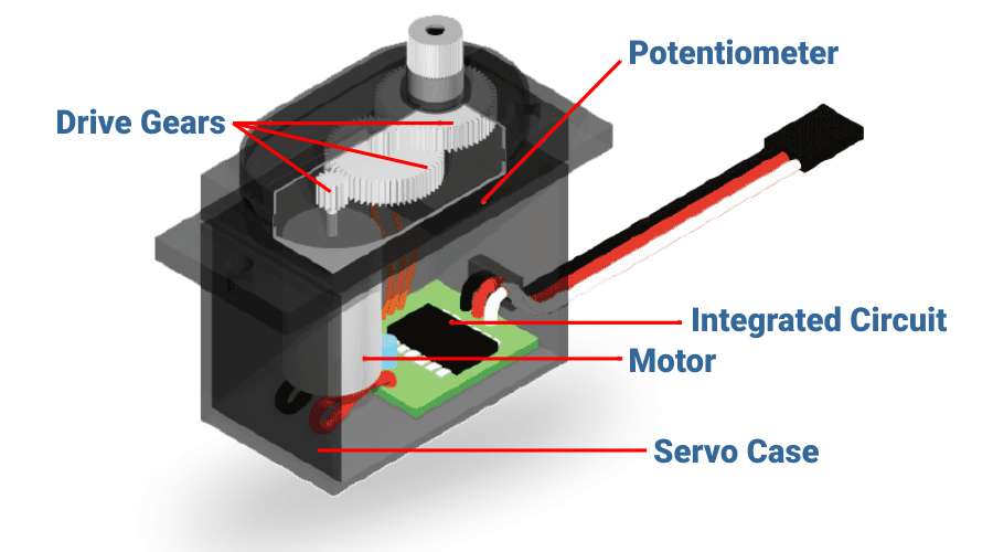
What’s inside the servo?
To fully understand how the servo works, you need to take a look under the hood. Inside there is a pretty simple set-up: a small DC motor, potentiometer, and a control circuit. The motor is attached by gears to the control wheel. As the motor rotates, the potentiometer’s resistance changes, so the control circuit can precisely regulate how much movement there is and in which direction.
When the shaft of the motor is at the desired position, power supplied to the motor is stopped. If not, the motor is turned in the appropriate direction. The desired position is sent via electrical pulses through the signal wire. The motor’s speed is proportional to the difference between its actual position and desired position. So if the motor is near the desired position, it will turn slowly, otherwise it will turn fast. This is called proportional control. This means the motor will only run as hard as necessary to accomplish the task at hand.
Servos are controlled by sending an electrical pulse of variable width, or pulse width modulation (PWM), through the control wire. There is a minimum pulse, a maximum pulse, and a repetition rate. A servo motor can usually only turn 90° in either direction for a total of 180° movement. The motor’s neutral position is defined as the position where the servo has the same amount of potential rotation in the both the clockwise or counter-clockwise direction. The PWM sent to the motor determines position of the shaft, and based on the duration of the pulse sent via the control wire; the rotor will turn to the desired position. The servo motor expects to see a pulse every 20 milliseconds (ms) and the length of the pulse will determine how far the motor turns. For example, a 1.5ms pulse will make the motor turn to the 90° position. Shorter than 1.5ms moves it in the counter clockwise direction toward the 0° position, and any longer than 1.5ms will turn the servo in a clockwise direction toward the 180° position.

When these servos are commanded to move, they will move to the position and hold that position. If an external force pushes against the servo while the servo is holding a position, the servo will resist from moving out of that position. The maximum amount of force the servo can exert is called the torque rating of the servo. Servos will not hold their position forever though; the position pulse must be repeated to instruct the servo to stay in position.
Advantages and Disadvantages of a Servo
Because servo motors have an integrated circuit with logic controls they will increase the amount of current drawn as the load on the coil so there is no “out-of-step” condition. This also allows for high speed operation of the motor. Servos can tend to lag in their rotation so high precision control is not likely. Servos also are not suitable for loads that are as heavy as comparable simple DC and stepper motors. When stopped, the motor’s rotor continues to move back and forth one pulse. So that, it is not suitable if you need to prevent vibration.
ASSIGNMENT 4.1.3: Controlling a Servo
For this assignment you will learn some basic servo control through the Python environment on your Raspberry Pi. You will need your servo motor and three m-f jumper wires (red, black and one other color).
Follow the instructions in the assignment titiled Raspberry Pi Lab - Servo Control.
4.1.2.3 Stepper Motors
How a Stepper Motor Actually Works
Stepper motors are DC motors that move in discrete steps. They have multiple coils that are organized in groups called “phases”. By energizing each phase in sequence, the motor will rotate, one step at a time. With a computer controlled stepping you can achieve very precise positioning and/or speed control. For this reason, stepper motors are the motor of choice for many precision motion control applications. Stepper motors come in many different sizes and styles and electrical characteristics.
Animation of a simplified stepper motor (unipolar) Frame 1: The top electromagnet (1) is turned on, attracting the nearest teeth of the gear-shaped iron rotor. With the teeth aligned to electromagnet 1, they will be slightly offset from right electromagnet (2). Frame 2: The top electromagnet (1) is turned off, and the right electromagnet (2) is energized, pulling the teeth into alignment with it. This results in a rotation of 3.6° in this example. Frame 3: The bottom electromagnet (3) is energized; another 3.6° rotation occurs.
Advantages and Disadvantages of a Stepper Motor
Since the percentage step error does not accumulate as the motor rotates, it is able to run at wide range of speeds and ranges, including very slow speeds without reduction gearing. Stepper motor provide excellent response during start, stop and reverse mode. They are highly reliable since no brushes or commutators are used. Stepper motor control circuits are simple and low cost. However, Resonance occurs if it is not properly controlled and progressive loss of torque at high speeds may occur. Hence it is not easy to operate at extremely high speeds.
ASSIGNMENT 4.1.4: Controlling a Stepper Motor
Make a lab for the Stepper motor.
Follow the instructions in the assignment titiled Raspberry Pi Lab - Stepper Motor Control.
4.1.2.4 Linear Actuators and Lead Screws
A linear actuator is an actuator that creates motion in a straight line, in contrast to the circular motion of a conventional electric motor. Linear actuators are used in machine tools and industrial machinery, in computer peripherals such as disk drives and printers, in valves and dampers, and in many other places where linear motion is required. Hydraulic or pneumatic cylinders inherently produce linear motion.
4.1.3 Sensors
There are even more sensor types than there are actuator types. If we browse the Adafruit Sensor Page we see how limitless these possibilities are. For any type of sensor application there is, someone has though of a way to build it.
As this excerpt from a robotics text explains, sensors are either proprioceptive or exteroceptive and, at the same time, either passive or active. This chart is taken from that text:

A passive sensor is one which just ‘listens’ to what is happening. Examples include: - A light sensor which detects if a light is shining on it - An infra-red sensor which detects the temperature of an object
Sensors that send information to the environment and receive a response from that signal are known as active sensors.
ASSIGNMENT 4.1.?: Comparing Sensor Types
From your kit select the following sensors:
Follow the instructions in the assignment titiled Raspberry Pi Lab - Comparing Sensors.
4.1.4 Control Systems
For most students, the Raspberry Pi will function as the control system for the course. This is basically because we are learning to use it in class. Students learn to interact with the Pi using the command line and Python. In addition, the Raspberry Pi offers many advantages over other microprocessors like Arduinos. One of the main advantages is the built in wifi capabilities. This allows for remote programming and true Internet of Things (IoT) capabilites. Still, some may choose a different processor, maybe even a different version of the Pi.
A Raspberry Pi Zero W is an extremely compact and low cost alternative to the Rapberry Pi 4 we use in class. It is made for low-power, compact IoT applicaitons and should be considered. While the processor speed is slower than larger Pis, it might be just the fit for your project. The Raspberry Pi Foundation released a new microcontroller in the last year called the Pico. It is a great alternative if a full OS is not needed on your project. If you can just flash the memory and let it run, a microcontroller may be a good choice - not to mention, they are very inexpensive. Other control options, like the world famous Arduino, are available as well. This list is quite extensive and should be considered.
A third option is to build a control system from the ground up using a microprocessor and adding the necessary components to it. While this option is less likely, some students may find this as a requirement in a future college class so it is good to understand what this option involves. The reading below discusses these devices.
Now it is time to start thinking about how you will eventually control your project by evaluating your options.
ASSIGNMENT 4.?.?: Control Systems Overview
View this video. This is a video of a lecture given. While it is a little dry, it is an exceptional overview of MCUs and SBCs.
Make a chart which lists all the major MCU and SBCs from the blog article above. (Use the template that has been shared with you) Complete the chart by researching the differences between them all.
Write a summary of why you would use each one with examples. Finally, make a guess as to which one you think you will use for your capstone project next semester.
4.1.5 Structural Parts
The skeleton of the robotic system determines the physical constraints on the design. For years now, our robotics team has dealth with this issue. Several years ago they were presented with a challenge in the competition which required their robot to climb a mountain:

As we can see from the photograph, the mountain was quite daunting. The previous year, the team had advanced to the world championships and found that their robot, while the best design in Colorado, was not suited to compete with the heavier robots beyond the state. As a result they had been pushed around a bit and not been very successful. The solution to this was to weld a steel frame together and build the robot off of that. The result was a 70 pound robot! Without thinking more deeply about the design of the current year, they had hampered themselves by dealing with the previous yesr’s challenge in mind. The robot was robust and strong but could not climb the mountain. Instead, every tread system they tried to use to climb was under so much strain that it eventually broke. They would even 3D print treads made out of high strength plastics that still could not hold up to the strain. In this case, the structural parts let them down. What a great learning experience that was. All three of those students in the photo are in science and engineering programs currently in college. The one on the right, Mitchell Watson, is literally going to be a rocket scientist when he graduates for Cal Tech. Understanding these concepts of mechanical design are not only fundamental to robotics, they can lead to many great opportunities.
There are many options for structural parts. Over the years, we have accumulated a wealth of parts in our program which may be checked out. In addition, we have plenty of scrap material (we hated that mountain so much that we cut it up at the end of the season and have been using it for scrap since then). After you learn how to use CAD later in this unit, you will be able to design and print your own custom parts as well.
The type of material matters. Begin with this materials guide in selecting your parts. Consider using pre-built kits or components. Here is a list of companies that provide robotics parts:
- Pitsco Education: Many different types of parts from a long-time vendor
- REV Robotics: Higher quality aluminum and high grade plastic parts
- GoBilda: Awesome parts for large applications
- 80/20 Inc.: Incredibly versitile structural systems
- RobotShop: If you are looking for a kit, to get started
- SparkFun: Based in Niwot, you can go visit them and pick up your parts or take the tour to get some ideas
NOTE: For any vendors, check before you buy. We have educational discounts with most all of them.
4.2 Mechanisms and Motion
Mechanisms can be used to change the speed, direction or force required to do something. Mechanisms may be able to help you but they cannot do it on their own.
4.2.1 Inputs and Outputs
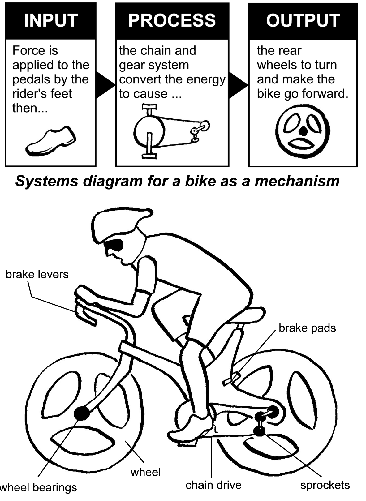
Machines need energy and someone or something to operate them. In mechatronics we utilze actuators attached to a control system for the source of the energy. The energy that is used by a machine is called the input. The result of this energy input is called the output. While it is not a robotic system, a mechanism such as a bicycle can be explained with the diagram below.
4.2.2 Types of Motion
Mechanisms are concerned with motion. There are four main types of motion. These can be illustrated by means of human body movements.

Motion that is transferred along a line is known as linear motion. Utilizing this system allows robotic designs to extend reach in all directions but is mainly used in attaining more height or reaching horizontally. Motion which is a repetitive up-and-down or back-and-forth linear motion is known as reciprocating motion. This movement is commonly used in pumps. Rotary motion is a circular movement of an object around a center (or point) of rotation and is the most commonly used motion in robotic systems. Drive systems are usually based in rotary motion but other systems utilize it as well including lifting and collecting mechanisms. Pendulums represent one application of oscillating motion which are used in robotics systems.
ASSIGNMENT 4.2.0: Mechanisms in Motion
Creating robotic motion begins with an understanding of the various types of motion. For this assignment you will seek out unique, robotic applications which illustrate the four types of mechanical motion discussed in this section.
Follow the instructions in the assignment titiled Mechanical Motion Overview.
4.3 Levers
One of the oldest mechanisms is the lever. Stone Age people used them to move large objects.

A lever can be described as a long rigid object with a pivot point somewhere along its length. The pivot is a fixed point about which the lever rotates. The pivot is also known as the fulcrum. Levers are used to do two things: they can move a large load with only a little effort, or they can increase or amplify movement. A seesaw is a simple example of a lever.

4.3.1 Classes and Categories
Levers are classified by the relative positions of the fulcrum (the point of fixed pivot), effort (the input force) and resistance (or load). It is common to call the input force the effort and the output force the load or the resistance. This allows the identification of three classes of levers by the relative locations of the fulcrum, the resistance and the effort.
With a class one lever, the fulcrum is between the effort and resistance. The effort is applied on one side of the fulcrum and the resistance (or load) on the other side, for example, a seesaw, a crowbar or a pair of scissors, a common balance , a claw hammer. Mechanical advantage may be greater than, less than, or equal to 1.

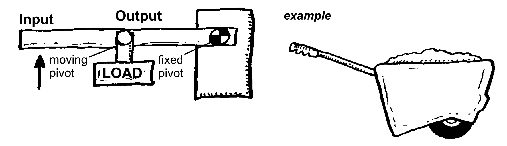
A class two lever places resistance (or load) between the effort and fulcrum. The effort is applied on one side of the resistance and the fulcrum is located on the other side, e.g. in a wheelbarrow, a nutcracker, a bottle opener or the brake pedal of a car, the load arm is smaller than the effort arm, and the mechanical advantage is always greater than one. It is also called force multiplier lever.
Utilizing a class three lever places the effort between the fulcrum and resistance. The resistance (or load) is on one side of the effort and the fulcrum is located on the other side, for example, a pair of tweezers, a hammer, a pair of tongs, fishing rod, common balance or the mandible of our skull. The effort arm is smaller than the load arm. Mechanical advantage is always less than 1. It is also called speed multiplier lever.

4.3.2 Mechanical Advantage
We use levers every day because they make it is easier to get work done. They give us mechanical advantage (MA) which means that you can move a large load using a small effort. The MA in the example below is found by comparing the weight of the load with the effort needed to move it. (Remember 1kg = 10 Newton)
\[MA=(Load/Effort)=300N/100N=3:1 = 3\]
If you look at wheelbarrow example again you will see that the distance the effort has to move is much further that that of the load. By comparing the two distances you get the velocity ratio (VR).
\[VR=(D_2/D_1)=400mm/100mm=4:1=4\]

4.3.3 Efficiency
Mechanisms are not always 100% efficient due to factors such as parts that bend, friction etc. The scientific formula for the calculation of the efficiency of a mechanism is as follows:
\[Efficiency = (MA/VR)*100\%\] For the example of the wheel barrow above we can calculate efficiency using this formula.
\[Efficiency=(3/4)*100\%=75\%\]
4.3.4 Moments
If a seesaw is not moving but remains level, it is said to be balanced. The forces on either side of the fulcrum are equal and opposite. If the force on one end of the seesaw is greater than the other, or if the fulcrum is not in the center, then the seesaw will rotate around the fulcrum. This turning force is known as a moment.

Moments can be used to work out unknown weights or distances of movement. The figure below shows how to calculate the moment for a very large spanner.

We can calculate ways to create a balanced situation by applying these principles. Consider the seesaw example here:

ASSIGNMENT 4.3.0: Lever Design
Mechanical advantage may be attained by utilizing one of the oldest machines in human history, the lever. For this assighment you and your partner will build several levers, calculate mechanical advantage for each one and then test your results. Finally, you will consider real-world applications of these systems.
Follow the instructions in the assignment titiled Gaining the Advantage with Levers.
4.4 Rotary Motion
A rotation is a circular movement of an object around a center (or point) of rotation. The geometric plane along which the rotation occurs is called the rotation plane, and the imaginary line extending from the center and perpendicular to the rotation plane is called the rotation axis. A three-dimensional object can always be rotated about an infinite number of rotation axes.

4.4.1 Pulleys, Sprockets and Gears
Pulleys, sprockets and gears are used to transfer rotary motion from one place to another. All are wheels. Pulleys are wheels with grooves in the rims, in which a belt or rope can run. Pulleys can transfer rotary motion from one shaft to another or can be used to lift heavy loads. Gears are wheels with teeth evenly spaced around the rims. Several gears can be placed, so that their teeth interlock, or mesh. When two or more gears are used together, they form what is called a gear train. Gears can be used to change the speed and direction in which something rotates. When chains are used to connect the “gears”, a chain and sprocket system is formed, for example on bicycles and motorcycles. Sprocket systems share properties of both of the other systems.
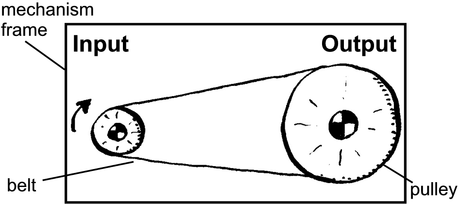
In the figure below, the direction of rotation of the pulleys is the same for each pulley. The driver pulley is attached to the drive system (input) while the driven pulley is attached to the actuational output. The mechanical advantage is gained by the variation in the size (diameter) of the pulleys. This mechanical advantage may be used to increase either velocity of rotation or torque (rotational force).
The next figure illustrates a pulley system which switches the direction of each pulley. All calculations made on a twisted pulley are the same as a simple pulley system.

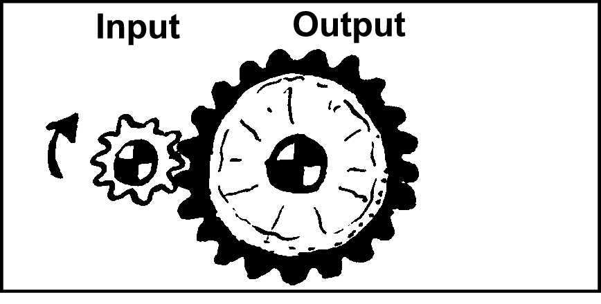
Unlike pulleys, the driven gear which is attached to the actuation device (input) rotates in the opposite direction as the driver gear which is attached to the acutational output.
By placing an idler gear of the same size as either of the other two gears, the direction of the driven gear may be reversed so that it rotates in the same way as the driver gear without changing the rotational speed or torque of the output.
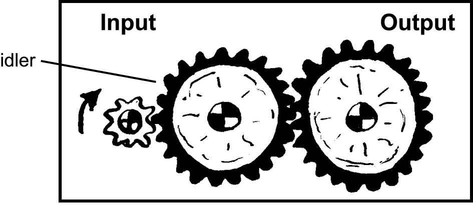
This configureation is known as a gear train.
In order to increase the velocity ratio or mechanical advantage of a pulley or gear system, compound pulley and gear trains may be constructed.


A NOTE ABOUT SPROCKETS AND CHAINS: As previously mentioned, sprockets and chains combine characteristics of the both gears and pulleys. While the driver sprocket and the driven sprocket move in the same direction like pulleys, they have teeth which a chain can fit into to provide added stregth to the system, as in the case of gears. Considerations for choosing the correct system for your application are below:
Advantages of tooth gears and chains:
- Greater forces can be transferred
- Chains do not slip/slide
- Chains can be disassembled for removal
Advantages of pulleys and belts:
- Belts are not noisy
- Belts can be stretched for fitting and for removal
- Crossed belts can change the direction of rotation
All of the formulas in the next section are the same for sprockets as for pulleys and gears. Typically, the number of teeth on the sprocket are used to calculate the velocity ratio as in the case of gears.
The illustration below shows gears fixed to parallel shafts, forming a simple gear train. The gear fixed on the drive shaft is called the driver gear and is connected to the driven gear. The shafts will turn in opposite directions and, because the gears have different sizes, they will turn at different speeds.

The difference in their speeds (velocity ratio) can be calculated from the number of teeth on the driver gear (Teeth1) compared to the driven gear (Teeth2).
\[VR = (Teeth_2/Teeth_1) = (40/20) = 2:1\] The velocity ratio (VR) in this example may be expressed as 2:1 (say “two to one”) or simply as 2. This means that in this case the driver shaft must turn twice for the driven shaft to complete one turn.
Similarly, the velocity ratio of a pulley system may be calculated with essentially the same formula. Pulley systems use a belt to transmit motion and force from the driver shaft to the driven shaft. Cars use a pulley system with V-belts running in grooves on the pulley wheels. Speed changes are made by using different sizes of pulleys on the driver and driven shafts respectively. By comparing the sizes of the two pulleys you can calculate the velocity ratio (VR) of the system. Instead of using the number of teeth, the difference in pulley speeds can be calculated by comparing the diameter of the driver pulley (Size1) to the diameter of the driven pulley (Size2).
\[VR = (Size_2/Size_1)=(25/100)=1:4\] The velocity ration in this example is expressed as 1:4. This means that one turn of the driver shaft will give four turns of the driven shaft.
Once we know the velocity ratio of the gears we are working with, we can begin to predict output speed (SO) for a given input speed (SI).
\[S_O=(S_I/VR)=(2000rpm/3:1)=6000rpm\] In this case the velocity ratio is 3:1 and the input speed is 2000 revolutions per minute (rpm). The resulting output speed is 6,000 rpm.
The Bevel Gear
A special class of gears known as bevel gears may be used to change the axis of rotation of a rotary motion system. Bevel gears may be used where the axes of the two shafts intersect and the tooth-bearing faces of the gears themselves are conically shaped. Bevel gears are most often mounted on shafts that are 90 degrees apart, but can be designed to work at other angles as well. The pitch surface of bevel gears is a cone.

Common applications of this may be seen in automobies. The easiest to recognise is the rear differential as seen below.
![]()
Worm Drives
A worm drive is a gear arrangement in which a worm (which is a gear in the form of a screw) meshes with a worm wheel (which is similar in appearance to a spur gear). The two elements are also called the worm screw and worm gear.

ASSIGNMENT 4.4.0: Rotary Advantage
Learning to utilize various rotary motion systems can allow us to leverage the laws of physics. In this assignment we will explore various rotational force systems to increase both speed and torgue.
Follow the instructions in the assignment titiled Pulleys-Sprockets-Gears in Action.
4.5 Linear Motion
Linear motion is the most basic of all motion. According to Newton’s first law of motion, objects that do not experience any net force will continue to move in a straight line with a constant velocity until they are subjected to a net force. Under everyday circumstances, external forces such as gravity and friction can cause an object to change the direction of its motion, so that its motion cannot be described as linear.
A unique challenge in a robotic system is converting rotary motion to linear motion. There are two mahory systmes for accomplishing this task as outlined below.
4.5.1 Rack and Pinion Systems
A rack and pinion is a type of linear actuator that comprises a circular gear (the pinion) engaging a linear gear (the rack), which operate to translate rotational motion into linear motion. Driving the pinion into rotation causes the rack to be driven linearly. Driving the rack linearly will cause the pinion to be driven into a rotation. A rack and pinion drive can use both straight and helical gears. Helical gears are preferred due to their quieter operation and higher load bearing capacity. The maximum force that can be transmitted in a rack and pinion mechanism is determined by the tooth pitch and the size of the pinion.

4.5.2 Lead Screws
A lead screw, also known as a power screw or translation screw, is a screw used as a linkage in a machine, to translate turning motion into linear motion. Because of the large area of sliding contact between their male and female members, screw threads have larger frictional energy losses compared to other linkages. They are not typically used to carry high power, but more for intermittent use in low power actuator and positioner mechanisms. Lead screws are commonly used in linear actuators, machine slides (such as in machine tools), vises, presses, and jacks. Lead screws are a common component in electric linear actuators.
The linear actuator described above utilizes a lead screw to turn rotational force into linear force.
ASSIGNMENT 4.5.0: Potential Linear Motion Applications
Learning to utilize various rotary motion systems can allow us to leverage the laws of physics. In this assignment we will explore various rotational force systems to increase both speed and torgue.
Follow the instructions in the assignment titiled Applyting Linear Motion.
4.6 Drive Systems
The purpose of the drivetrain is to facilitate the movement of the robot, and thus is crucial to the overall function of the robot. If the drivetrain doesn’t work, the rest of the robot won’t work either. When building any mechanism, it is wise to list some necessities or desired features.
4.6.1 Factors to Consider
Reliability: Reliability starts with the drivetrain, the foundation to any robot. One aspect of reliability to consider is the type of motor and gearbox that is used in the drivetrain. One should always consider how much load will be placed on the system and select accordingly.
Agility: There are many factors to agility: top speed, acceleration, turning radius, turn speed, and ability to strafe. Note that turning radius is an often overlooked feature that is critical to the overall agility of the drivetrain.
Traction/Pushing Power: While this feature is often overemphasized, it is still very important. Pushing power describes a drivetrain’s ability to endure defense/engage in defense. In addition, traction will be important if the drivetrain must traverse obstacles or some sort of terrain. Many factors affect the pushing power of a drivetrain, including wheel type, motor gearing, and overall weight of the robot.
Powering the drivetrain: Generally, there are four options for power transmission: direct drive, chain, gear, and belt. Direct drive systems place the wheel directly on the motor shaft. This has the disadvantage of subjecting that gearbox to unusual amounts of stress. If possibel, indirect transmissions such as belts and chains are preferred.
ASSIGNMENTs 4.6.0: Examining Drivetrain Systems
Since many students will chose to build a mobile robotic platform at some point, it is useful to examine the various mobile systems. One organization which competes in the First Tech Challenge has compiled an overview of many types of drivetrains. We will use that resource as the basis for our study of drivetrain systems.
Take a look at these various drivetrain systems commonly used on robots:
Pick the two that are most interesting to you. In two well-developed paragraphs, describe the drivetrains and explain the advantages and disadvantages of those drive systems. Compare the various applications which would make one or the other more desirable. Include correct usage of the four “factors to consider” listed above in your paragraph in order to demonstrate your understanding of those concepts.
4.7 Computer Aided Design
The concepts learned in this unit require planning and modeling to implement effectively. It is useful to “tinker” with mechanical parts in order to be able to visualize the system itself. All engineering, however, includes a significant design element. In most cases, we need to sketch out our design on a piece of paper or board to give the solution to our problem some conceptual scale.
Once you have your design down on paper, it is time to create it like a real mechatronics engineer. For this section you will learn to use OnShape, a modern and full-scale computer aided design (CAD) system. OnShape was founded by two engineers at SolidWorks which is still considered the gold standard of CAD. SolidWorks comes with a hefty price tag, even for students. OnShape is free to secondary schools. As a result, we will use it. Once year learn this tool, switching to other CAD software will be relatively painless. In addition, it is entirely web based so you can use it as long as you have an internet connection and a web browser.
If you have not done so already, head to the OnShape Account Setup section of the course book. Follow those instructions. After you have done this, log on to your account and follow these instructions:
Click on the “Learning Center Button”

Select “Self-Paced Courses > Learning Pathways”

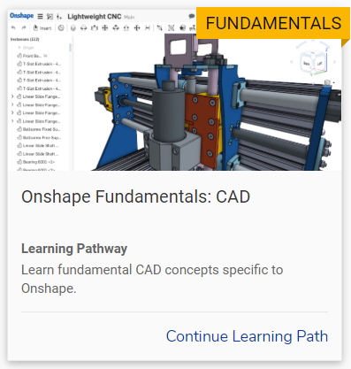
Select “OnShape Fundamentals: CAD”
ASSIGNMENTs 4.7.0: CAD Fundamentals
For this part of our course you may move at your own pace to complete these assignments. Each one requires you to work through the CAD concepts and skills listed in the OnShape courses below.
Complete the first five courses in this learning pathway:- Navigating Onshape
- Introduction to Sketching
- Part Design Using Part Studios
- Multi-Part Part Studios
- Onshape Assemblies