Section 2 Introduction
2.1 A Brief Overview of the Course
Remember that engineers spend a majority of their time debugging their designs. You will too. It is not because this course is made too hard for you…it is just the way engineering works.

“They say that no plan survives first contact with implementation. I’d have to agree.”
– Mark Watney, Sol 40
Why begin with this quote? One of my favorite books and movies of all time is The Martian. The struggles of the main character, Mark Whatney, demonstrate the challenges facing engineers. While we will not be risking our lives on another planet, our solutions to the problems in this course, follow the same pattern as his. Where he sought to survive being the only human on another planet by engineering his way out, we will survive this course by learning to attack problems in the same way and remember not to give up. We must keep in mind, no plan will work the first time.
During this class students will explore the field of mechatronics using a variety of hands-on activities. Students begin the semester with an introduction to basic history and theory of robotics, the engineering process and tools used to create robotic devices. We will introduce basic electronics concepts. We will examine various types of mechanical mechanisms from simple machines to more complex drive systems. Moving forward, programming becomes an essential and vital element. Students program the onboard micro-processor found on a Raspberry Pi 4B+. This control board will use the Raspian OS which is a version of Linux. While students will work within the Linux shell, the programming language of this course is Python. Students work individually and in teams to design and build simple and complex mechatronic systems capable of meeting a variety of criteria including driving, pushing, controlling speed, etc. Sensors are introduced to allow robotic devices to interact with the environment. Actuator design is discussed and different manipulator systems are introduced. As an essential part of mechanical design, students will be exposed to CAD concepts using OnShape.

As you can see from this Euler diagram here, Mechatronics is a complicated field of engineering that combines many areas of study. This is the more technical name for robotics and was created by Tetsuro Mori in 1971 and has served as the name for this field since. In this course, you will be introduced to several of the areas on this diagram.
Since you may need to work at home from time to time on projects for this course, be sure that you consider creating a good remote learning environment by doing the following:
- Create a dedicated workspace for yourself that you can keep neat and organized throughout the year. Pick a place that is as quiet as possible so that you can concentrate. Do not use this space for anything else. In this course that space should include a place for your computer as well as an area to work on electronics projects - preferable with a hard surface like a desktop or workbench.
- Manage your sleep schedule. You will need to be able to concentrate and stay focused since you do not have a teacher hovering over your workspace to keep you focused. If you go to bed at a consistent time and wake up at a consistent time, you will be able to learn more effectively.
- Make sure you know how to log on to every account needed for the course. See the Prerequisites for all of the details for this course. Be sure to ask questions if you encounter any difficulties.
2.2 History of Robotics
Adapted from Robotics: A Brief History, Stanford University
Origins of “Robot” and “Robotics”
The word “robot” conjures up a variety of images, from R2D2 and C3PO of Star Wars fame; to human-like machines that exist to serve their creators (perhaps in the form of the cooking and cleaning Rosie in the popular cartoon series the Jetsons); to the Rover Sojourner, which explored the Martian landscape as part of the Mars Pathfinder mission. Some people may alternatively perceive robots as dangerous technological ventures that will someday lead to the demise of the human race, either by outsmarting or outmuscling us and taking over the world, or by turning us into completely technology-dependent beings who passively sit by and program robots to do all of our work. In fact, the first use of the word “robot” occurred in a play about mechanical men that are built to work on factory assembly lines and that rebel against their human masters. These machines in R.U.R. (Rossum’s Universal Robots), written by Czech playwright Karl Capek in 1921, got their name from the Czech word for slave.

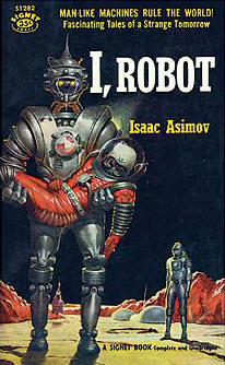
The word “robotics” was also coined by a writer. Russian-born American science-fiction writer Isaac Asimov first used the word in 1942 in his short story “Runabout.” Asimov had a much brighter and more optimistic opinion of the robot’s role in human society than did Capek. He generally characterized the robots in his short stories as helpful servants of man and viewed robots as “a better, cleaner race.” Asimov also proposed three “Laws of Robotics” that his robots, as well as sci-fi robotic characters of many other stories, followed:
- A robot may not injure a human being or, through inaction, allow a human being to come to harm.
- A robot must obey the orders given it by human beings except where such orders would conflict with the First Law.
- A robot must protect its own existence as long as such protection does not conflict with the First or Second Law.
- Added later is the Zeroth Law to precede the others: A robot may not harm humanity, or, by inaction, allow humanity to come to harm.
Early Conceptions of Robots
One of the first instances of a mechanical device built to regularly carry out a particular physical task occurred around 3000 B.C.: Egyptian water clocks used human figurines to strike the hour bells. In 400 B.C., Archytus of Taremtum, inventor of the pulley and the screw, also invented a wooden pigeon that could fly. Hydraulically-operated statues that could speak, gesture, and prophecy were commonly constructed in Hellenic Egypt during the second century B.C.
In the first century A.D., Petronius Arbiter made a doll that could move like a human being. Giovanni Torriani created a wooden robot that could fetch the Emperor’s daily bread from the store in 1557. Robotic inventions reached a relative peak (before the 20th century) in the 1700s; countless ingenius, yet impractical, automata (i.e. robots) were created during this time period. The 19th century was also filled with new robotic creations, such as a talking doll by Edison and a steam-powered robot by Canadians. Although these inventions throughout history may have planted the first seeds of inspiration for the modern robot, the scientific progress made in the 20th century in the field of robotics surpass previous advancements a thousandfold.
The First Programmable System
There is very little doubt today about both how essential programming is to robotics and who the earliest computer programmer was. While many would immediately think of modern computer scientists like Steve Wozniak or earlier programmers like Alan Turing, the first person to successfully put forth the idea of a programmable system like a computer was Ada Lovelace. In her article of 1842 (Yes, during the John Tyler administration) she proposed that numbers and objects could be used to “express abstract scientific operations” and create action based on rules. This was the first time anyone had proposed programming a device to act on inputs based on rules. This is the very heart of what it is to be a robot. Despite the great disadvantage of being born a woman in a very male dominated 19th century, she founded the field which would become the backbone of mechatronics.

The Origins of the Math of Robotics
The backbone of decision making in the mechatronics is a field of math called Boolean Algebra. As a professor of mathematics at Queen’s College Cork in Ireland, George Boole published a work titled An Investigation of the Laws of Thought in 1854. Boole sought to prove mathematically the existence of god through the application of logic. While his success at justifying the existence of god has not been supported, the underlying mathematical system that he invented would be used a century later as the foundation for modern day computers.
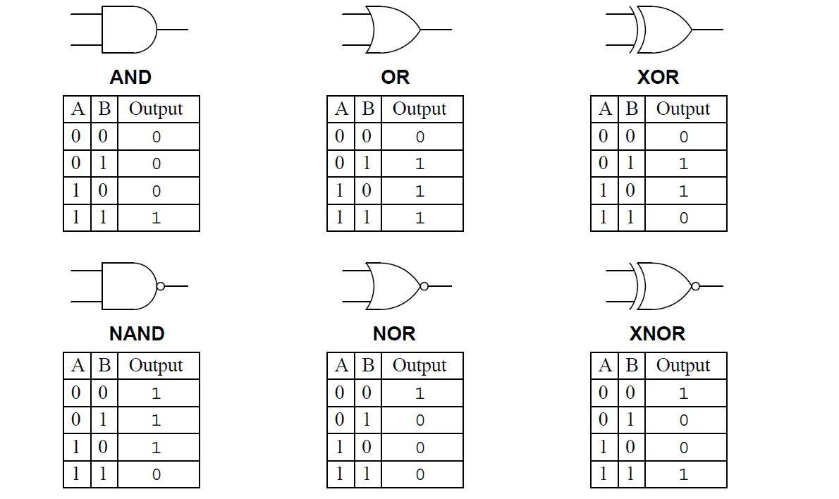
Without Boole’s contribution to mathematics and logic, modern microprocessers built from transistors would not be possible. While he lived in obscurity during his life, the long legacy of George Boole is found in every computer programming language, including Python. The code below, which you will become familiar with this year, demonstrates this application.
  While True:
        print("Boolean Algebra makes computer decision making possible.")
For a more in-depth understanding of his contributions to mechatronics see the embedded video in the Supplemental Videos Section.
The First Modern Robots
The earliest robots as we know them were created in the early 1950s by George C. Devol, an inventor from Louisville, Kentucky. He invented and patented a reprogrammable manipulator called “Unimate,” from “Universal Automation.” For the next decade, he attempted to sell his product in the industry, but did not succeed. In the late 1960s, businessman/engineer Joseph Engleberger acquired Devol’s robot patent and was able to modify it into an industrial robot and form a company called Unimation to produce and market the robots. For his efforts and successes, Engleberger is known in the industry as “the Father of Robotics.”

Academia also made much progress in the creation new robots. In 1958 at the Stanford Research Institute, Charles Rosen led a research team in developing a robot called “Shakey.” Shakey was far more advanced than the original Unimate, which was designed for specialized, industrial applications. Shakey could wheel around the room, observe the scene with his television “eyes,” move across unfamiliar surroundings, and to a certain degree, respond to his environment. He was given his name because of his wobbly and clattering movements. The Supplemental Videos section of this text has a video made about Shakey.
ASSIGNMENT 2.2.0: Git and GitHub Fundamentals
Let’s expand our knowledge of GitHub now. The goal of this course is to give you a brief introduction to GitHub. We’ll also provide you with materials for further learning and a few ideas to get you started on our platform.
Go to the Canvas page for this class and follow the instructions for “2.2.0 - Git and GitHub Fundamentals”.
2.3 The Metric System
This section is an adaptation of this page from Southeastern Louisiana University
The metric system is the preferred system of scientific units for several reasons:- The majority of countries in the world employ the metric system of measurement.
- The prefixes attached to metric units carry the same meaning for all base units.
-
The metric system is based upon powers of ten, which is convenient because:
- A measurement in the metric system that is represented by a rational number remains a rational number after metric unit conversion. (For example, 250 mm = 25 cm = .25 m). In contrast irrational unit systems , such as the English system, do not have the same property (For example, 250 inches = 20.8333… ft = 0.0039457… mile)
- Because metric units are decimal-based, they are easily converted by moving the decimal point.
The English System unit of mass is the slug, which when multiplied by the acceleration of gravity (32 ft/sec2) gives the weight in pounds.
The metric system uses the following base units:Unit of Measurement Name Abbreviation Length Meter m Mass Gram g Volume Liter L Frequently the above units are too small or more often too large to appropriately scale the measured quantity. It is then necessary to subdivide or expand our measurement unit. This will be discussed in the section on prefixes.
SI Units
The metric-based Systeme International or SI units are used to standardize the report or calculation of scientific quantities:
The SI units are used to construct all other units (these are called derived units). Some examples:Physical Quantity Name of Unit Abbreviation Length Meter m Mass Kilogram kg Temperature Kelvin K Time Second s Amount of Substance Mole mol Electric Current Ampere I Luminous Intensity Lumen Iv Property Symbol Dimensions Name Velocity v m s-1
Area A m2
Frequency v s-1 Hertz (Hz) Force F kg m s-2 Newton (N) Energy E kg m2 s-2 Joule (J)
To change the scale of the base units, prefixes are attached. A prefix represents a factor by which the base unit must be multiplied. Metric prefixes are listed below (The prefixes most-commonly used in chemistry are listed in red):
Prefix Symbol Decimal Value Power of Ten Exa- E 1,000,000,000,000,000,000
1018 Peta- P 1,000,000,000,000,000
1015 Tera- T 1,000,000,000,000
1012 Giga- G 1,000,000,000
109 Mega- M 1,000,000
106 Kilo- k 1,000
103 Hecto- h 100
102 Deka- da 10
101 (no prefix)
1
100 Deci- d 0 .1 10-1 Centi- c 0 .01 10-2 Milli- m 0 .001 10-3 Micro- µ 0 .000001 10-6 Nano- n 0 .000000001 10-9 Pico- p 0 .000000000001 10-12 Femto- f 0 .000000000000001 10-15 Atto- a 0 .000000000000000001 10-18 ASSIGNMENT 2.3.0: Metric System Practice
We will use metric prefixes and units of measure consistently this year to practice these systems complete the short assignment below:
Go to the Canvas page for this class and follow the instructions for “2.3.0 - Metric System Practice”.
2.4 Soldering Basics
Learning how to solder with proper soldering techniques is a fundamental skill everyone who works with electronics should master. In this tutorial, we outline the basics of soldering irons, soldering stations, types of solder, desoldering and safety tips. Whether you’re building a robot or working with Arduino, knowing how to solder will come in handy.
2.4.1 How to Solder
If you were to take apart any electronic device that contains a circuit board, you’ll see the components are attached using soldering techniques. Soldering is the process of joining two or more electronic parts together by melting solder around the connection. Solder is a metal alloy and when it cools it creates a strong electrical bond between the parts. Even though soldering can create a permanent connection, it can also be reversed using a desoldering tool as described below.
2.4.2 Soldering Tools
The good thing about learning how to solder is the fact that you don’t need a lot to get started. Below we’ll outline the basic tools and materials you will need for most of your soldering projects.
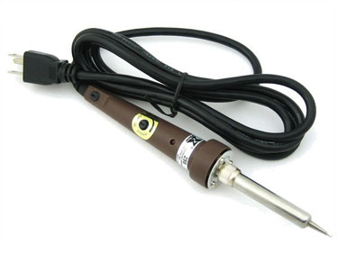
Soldering Iron
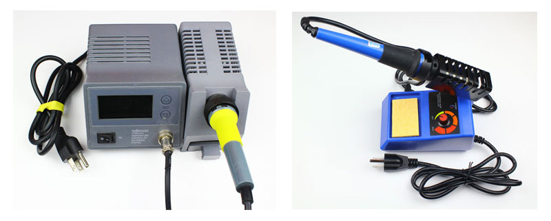
A soldering iron is a hand tool that plugs into a standard 120v AC outlet and heats up in order to melt solder around electrical connections. This is one of the most important tools used in soldering and it can come in a few variations such as pen or gun form. For beginners, it’s recommended that you use the pen style soldering iron in the 15W to 30W range. Most soldering irons have interchangeable tips that can be used for different soldering applications. Be very cautious when using any type of soldering iron because it can heat up to 896′ F which is extremely hot.
Soldering Station
A soldering station is a more advanced version of the basic standalone soldering pen. If you are going to be doing a lot of soldering, these are great to have as they offer more flexibility and control. The main benefit of a soldering station is the ability to precisely adjust the temperature of the soldering iron which is great for a range of projects. These stations can also create a safer workspace as some include advanced temperature sensors, alert settings and even password protection for safety.
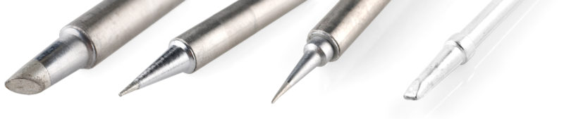
Soldering Iron Tips
At the end of most soldering irons is an interchangeable part known as a soldering tip. There are many variations of this tip and they come in a wide variety of shapes and sizes. Each tip is used for a specific purpose and offers a distinct advantage over another. The most common tips you will use in electronics projects are the conical tip and the chisel tip.
Conical Tip – Used in precision electronics soldering because of the fine tip. Because of its pointed end, it’s able to deliver heat to smaller areas without affecting its surroundings.
Chisel Tip – This tip is well-suited to soldering wires or other larger components because of its broad flat tip.
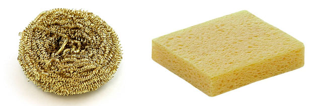
Brass or Conventional Sponge
Using a sponge will help to keep the soldering iron tip clean by removing the oxidation that forms. Tips with oxidation will tend to turn black and not accept solder as it did when it was new. You could use a conventional wet sponge but this tends to shorten the lifespan of the tip due to expansion and contraction. Also, a wet sponge will drop the temperature of the tip temporarily when wiped. A better alternative is to use a brass sponge as shown on the left.
Soldering Iron Stand
A soldering iron stand is very basic but very useful and handy to have. This stand helps prevent the hot iron tip from coming in contact with flammable materials or causing accidental injury to your hand. Most soldering stations come with this built in and also include a sponge or brass sponge for cleaning the tip.

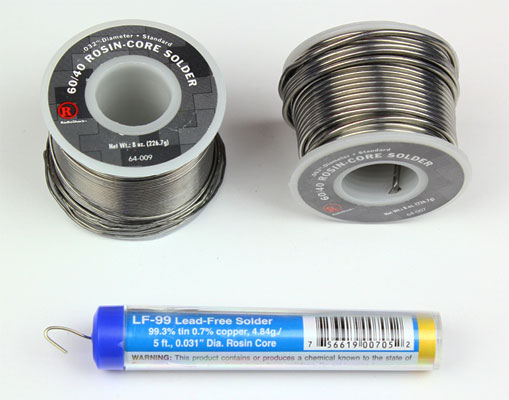
Solder
Solder is a metal alloy material that is melted to create a permanent bond between electrical parts. It comes in both lead and lead-free variations with diameters of .032″ and .062″ being the most common. Inside the solder core is a material known as flux which helps improve electrical contact and its mechanical strength.
For electronics soldering, the most commonly used type is lead-free rosin core solder. This type of solder is usually made up of a Tin/Copper alloy. You can also use leaded 60/40 (60% tin, 40% lead) rosin core solder but it’s becoming less popular due to health concerns. If you do use lead solder, make sure you have proper ventilation and that you wash your hands after use.
When buying solder, make sure NOT to use acid core solder as this will damage your circuits and components. Acid core solder is sold at home improvement stores and is mainly used for plumbing and metal working.
As mentioned earlier, solder does come in a few different diameters. The thicker diameter solder (.062″) is good for soldering larger joints more quickly but it can make soldering smaller joints difficult. For this reason, it’s always a good idea to have both sizes on hand for your different projects.
Helping Hand (Third Hand)
A helping hand is a device that has 2 or more alligator clips and sometimes a magnifying glass/light attached. This clips will assist you by holding the items you are trying to solder while you use the soldering iron and solder. A very helpful tool to have in your makerspace.

2.4.3 Soldering Safety
Now that you know what tools and materials are required, it’s time to briefly discuss ways of staying safe while soldering.
Soldering irons can reach temperatures of 800′ F so it’s very important to know where your iron is at all times. We always recommend you use a soldering iron stand to help prevent accidental burns or damage.

Make sure you are soldering in a well ventilated area. When solder is heated, there are fumes released that are harmful to your eyes and lungs. It’s recommended to use a fume extractor which is a fan with a charcoal filter that absorbs the harmful solder smoke you can visit sites like Integrated Air Systems for air filtration systems.
It’s always a good idea to wear protective eye wear in case of accidental splashes of hot solder. Lastly, make sure to wash your hands when done soldering especially if using lead solder.
2.4.4 How To Solder
There are multiple applications for the skill of soldering. One of the more useful soldering skills is soldering circuit boards.
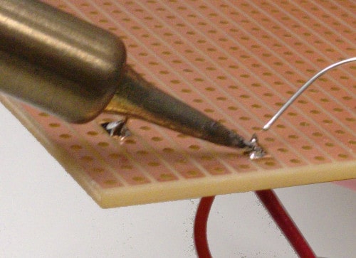
Step 1: Mount The Component – Begin by inserting the leads of the LED into the holes of the circuit board. Flip the board over and bend the leads outward at a 45′ angle. This will help the component make a better connection with the copper pad and prevent it from falling out while soldering.

Step 2: Heat The Joint – Turn your soldering iron on and if it has an adjustable heat control, set it to 400’C. At this point, touch the tip of the iron to the copper pad and the resistor lead at the same time. You need to hold the soldering iron in place for 3-4 seconds in order to heat the pad and the lead.

Step 3: Apply Solder To Joint – Continue holding the soldering iron on the copper pad and the lead and touch your solder to the joint. IMPORTANT – Don’t touch the solder directly to the tip of the iron. You want the joint to be hot enough to melt the solder when it’s touched. If the joint is too cold, it will form a bad connection.

Step 4: Snip The Leads – Remove the soldering iron and let the solder cool down naturally. Don’t blow on the solder as this will cause a bad joint. Once cool, you can snip the extra wire from leads.
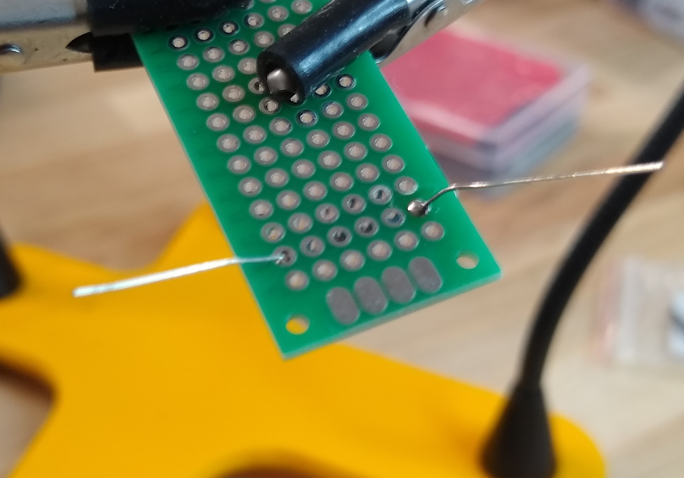
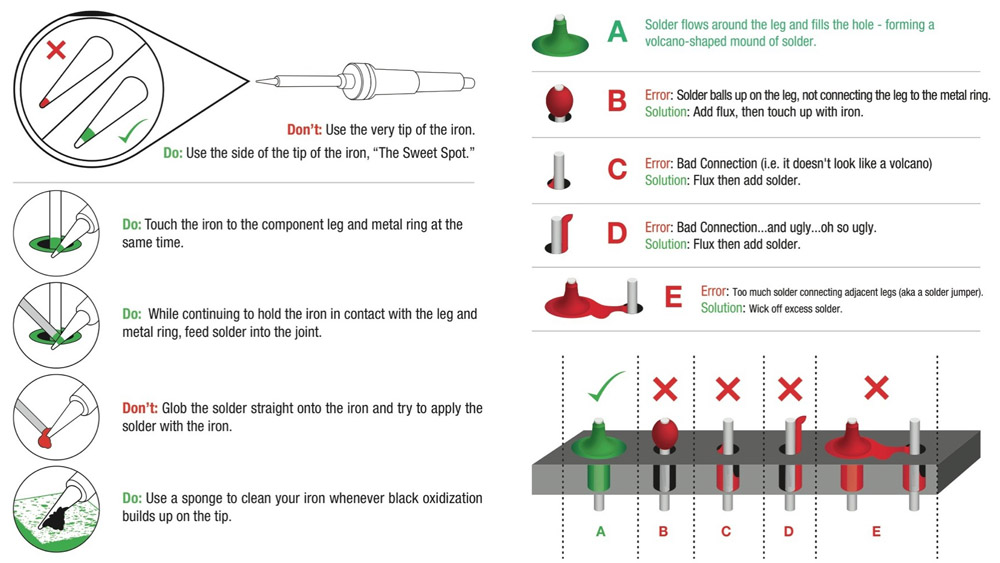
A proper solder joint is smooth, shiny and looks like a volcano or cone shape. You want just enough solder to cover the entire joint but not too much so it becomes a ball or spills to a nearby lead or joint.
2.4.5 How To Solder Wires
Now it’s time to show you how to solder wires together. For this process, it’s recommended to use helping hands or other type of clamp device.
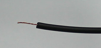
Step 1 - Begin by removing the insulation from the ends of both wires you are soldering together. If the wire is stranded, twist the strands together with your fingers.
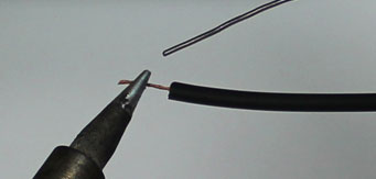
Step 2 - Make sure your soldering iron is fully heated and touch the tip to the end of one of the wires. Hold it on the wire for 3-4 seconds.
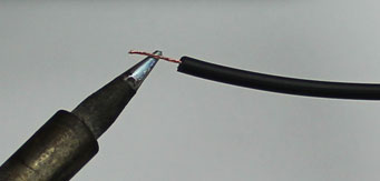
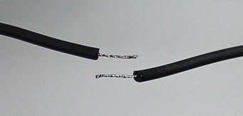
Step 3 - Keep the iron in place and touch the solder to the wire until it’s fully coated. Repeat this process on the other wire.
Step 4 - Hold the two tinned wires on top of each other and touch the soldering iron to both wires. This process should melt the solder and coat both wires evenly.
Remove the soldering iron and wait a few seconds to let the soldered connection cool and harden. Use heat shrink to cover the connection.
2.4.6 Desoldering
The good thing about using solder is the fact that it can be removed easily in a technique known as desoldering. This comes in handy if you need to remove a component or make a correction to your electronic circuit.
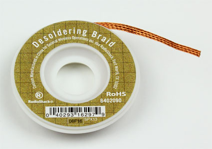
To desolder a joint, you will need solder wick which is also known as desoldering braid.
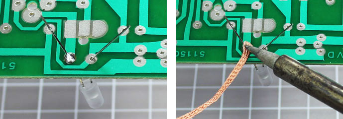
Step 1 – Place a piece of the desoldering braid on top of the joint/solder you want removed.
Step 2 – Heat your soldering iron and touch the tip to the top of the braid. This will heat the solder below which will then be absorbed into the desoldering braid. You can now remove the braid to see the solder has been extracted and removed. Be careful touching the braid when you are heating it because it will get hot.
Optional – If you have a lot of solder you want removed, you may want to use a device called a solder sucker. This is a handheld mechanical vacuum that sucks up hot solder with a press of a button.
To use, press the plunger down at the end of the solder sucker. Heat the joint with your soldering iron and place the tip of the solder sucker over the hot solder. Press the release button to suck up the liquid solder. In order to empty the solder sucker, press down on the plunger.
ASSIGNMENT 2.4.0 - Soldering: The Chapstick Flashlight
In order to practice our soldering skills, we will build a flashlight using a Chapstick Tube, an LED, a resistor, some wires and a 12V battery.
Go to the Canvas page for this class and follow the instructions for “2.4.0 - Soldering: The Chapstick Flashlight”.
2.5 Controlling the Raspberry Pi with Your Chromebook and a USB Cable
It is not necessary to use a monitor, keyboard and mouse with your Raspberry Pi. While this is an option, it would take up far too much space in the lab to be practical. Instead, we will use a process known as Secure Shell (SSH) Protocol. For the first part of our class, you will connect your Raspberry Pi to your Chromebook through the USB-B to USB-C cable in your kit. This will both provide power for your device and create a network connection to the Pi from the Chrome OS.
TAKE NOTE!
For this class, we will not use a Graphical User Interface (GUI) with our Pis. Instead we will code directly into the Linux Terminal of the Pi. This takes some practice if one has never used a coding window before. In the end, it is much faster to use a terminal than a GUI and this is the reason why code developers use keyboard shortcuts more often than a mouse. Don’t give up if this is not easy at first, with practice you will get better at it!
2.5.1 Add the SSH Application and Connect to the Pi
- To add the Chrome App for our SSH client, navigate to this extension on the Chrome Web Store.
- Click “Add to Chrome”.
- The extension should appear pinned to the top of your browser with your other extensions. If not, click the extensions icon in the upper right corner of your browser and make sure the “pin” next to the SSH extension is blue as it is here. If not, click it:

- To open the app, click on the icon that appears at the top of the browser window in the extension tray.

- Choose the “Connection Dialog” command. A box like this will appear:

In the username box, type “pi” and in the hostname box, type “10.55.0.1”. In the port box, type “22”.
Connect (Enter) and select “Allow” in the pop-up.
Type “yes” into the first pop-up and hit Enter.
The initial password for your Pi is "“WHSUpton01”.
If everything works, the Linux version will be displayed along with the last login date and IP address. The last line displays the terminal prompt for the device. It looks like this:

- Finally, you need to change your password. Type
sudo raspi-configin the terminal. Enter the default password if requested. You will get a screen that looks like this:

- Choose option 1 and press enter. Arrow down to “S3 Password” and press enter. Press enter to select “OK”. Enter your new password and confirm. Press enter to select “OK”. Arrow down to “Finish” and press enter.
- Its always a good idea to reboot after changes like this so type
sudo rebootand press enter. You will lose the SSH connection until the pi reboots (~60 seconds). You may reconnect after that time and use your new password.
2.5.2 Test the connection with your first Python Script
ASSIGNMENT 2.5.0 - Blink: Test the SSH
Throughout the year, we will be writing Python scripts to control external hardware. This first script will use the equipment in the bag with “Python Demo” written on it. If you closed the SSH connection to the Pi from the earlier section, re-connect it.
Go to the Canvas page for this class and follow the instructions for “2.5.0 - Blink: Test the SSH”.